
The M.A.P. Study Guide is a list of notes I first developed during instrument-flight-instructor training because I needed a concise explanation of various approach profiles. Now that I am instructing instrument students, it seems this guide is the best tool for teaching missed approach identification with FAA charts. The Missed Approach Point and Missed Approach Track symbols on each chart profile can mean different things depending on the type of procedure.
![]() Study Guide Download – FAA format (2.8 MB)
Study Guide Download – FAA format (2.8 MB)
You might also want the Jeppesen charts format of the study guide.
Introduction
Reading a missed approach procedure is a critical step toward briefing and flying a complete instrument approach to an airport. The missed approach point is the position where the pilot must immediately climb away from the airport if the landing criteria of FAR 91.175(c) are not met. There are two challenges involved in reading the missed approach point:
Location
Where is the missed approach point? The profile view depicts the missed approach point as the beginning of a dashed line, as shown above. It is generally located between the final approach fix and the airport. However, only one missed approach point is depicted, and each procedure may have two or three different missed approach points. Common locations for a missed approach point include the runway threshold, the primary NAVAID for the approach, and the intersection of the glide slope with the decision altitude.
Identification
How does the pilot know when the aircraft has reached the missed approach point? The pilot must understand the aircraft position relative to the missed approach point while flying each instrument approach procedure. Because each procedure has a unique configuration, the indications and techniques used to identify the missed approach point may be unique as well. Common identifiers for a missed approach point include a named waypoint, a DME fix, and a time and speed table.
This study guide contains several scenarios that illustrate the most common types of instrument approach configurations. These can be used as examples for learning to read and identify the location of a missed approach point.
Scenario #1: ILS Approach
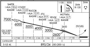
On an ILS, the missed approach point is that point at which the glide slope intersects the Decision Altitude (DA).
In this example, the climb to 1,100 ft is initiated upon reaching 895 ft and deciding to go missed.
In case of an early missed approach, the pilot would rely on DME or RADAR to approximate crossing the missed approach point before making the left turn.
The point depicted as (TICUD) is called a Computer Navigation Fix.
Scenario #2: LOC Approach without DME
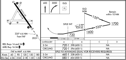
On the example LOC, the missed approach point can be identified only by flying a timed leg using a clock. The climb to 3,000 ft is initiated when the final approach time expires, and the right turn can be made at or beyond that point. In general, it is “inadvisable or impossible” to execute a normal landing from the missed approach point of a non-precision approach procedure. The missed approach point is the same for straight-in and circling approaches.
In case of an early missed approach, the pilot would maintain the approach speed and cross the missed approach point before making the right turn.
The profile for a LOC approach is essentially identical to VOR and NDB approaches. VOR and LOC approaches are relatively rare without DME, but they help to explain the following procedures that are more complex. NDB approaches usually do not have DME service.
A runway fix is sometimes depicted at the missed approach point, as in the KDET NDB RWY 15. This might serve as a quasi-DME for GPS equipped pilots.
Scenario #3: LOC Approach with DME

On the example LOC, the missed approach point is 1.5 DME from the IMT VOR/DME. The climb to 3,100 ft is initiated at or before 1.5 DME, and the left turn can be made at or beyond 1.5 DME. In general, it is “inadvisable or impossible” to execute a normal landing from the missed approach point of a non-precision approach procedure (the descent angle from 1.5 DME in this example would be 5.6 degrees). The missed approach point is the same for straight-in and circling approaches.
To use DME in identifying the missed approach point, the DME number must be published in the procedure, which is not always the case.
Not pictured in the excerpt above is the airport sketch from this procedure which states, “5.3 NM from FAF.” According to an FAA document (Control # 12-02-257) this is called the Airport Sketch Final Approach Course. It can be depicted six different ways and may or may not represent the location of a missed approach point. It is therefore incorrect, when briefing any procedure, to use the arrow in the airport sketch to identify the missed approach point.
Scenario #4: ILS or LOC Approach with DME
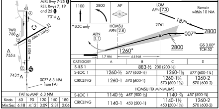
On an ILS, the missed approach point is that point at which the glide slope intersects the Decision Altitude (DA). This is depicted by “the beginning of the dotted missed approach course line” in profile view.
On the example LOC, the missed approach point is 1.1 DME from the APN VORTAC. The climb to 1,100 ft is initiated at or before 1.1 DME, and the left turn can be made at or beyond 1.1 DME. In general, it is “inadvisable or impossible” to execute a normal landing from the missed approach point of a non-precision approach procedure. If not equipped with DME or a GPS substitute, the missed approach point can be identified by flying a timed leg using a clock. The missed approach point is the same for straight-in and circling approaches, but is different from the ILS. The missed approach course for straight-in LOC or circling is not depicted in profile view.
A common mistake when briefing this type of procedure is to state that the missed approach point is 6.3 NM from the final approach fix, which is depicted four different ways in the profile view and airport sketch. The correct way to identify the missed approach point is by using 1.1 DME, which is 6.2 DME beyond the final approach fix. Notice they are not the same numbers.
This type of approach is named LDA if not aligned within 3° of the runway centerline. The lines of minima are named LDA/GS instead of S-ILS, and LDA instead of S-LOC. The profile is essentially identical, but LDA/GS is considered an APV type rather than a precision type.
Scenario #5: ILS or LOC Approach without DME
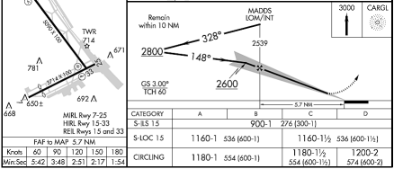
On an ILS, the missed approach point is that point at which the glide slope intersects the Decision Altitude (DA). This is depicted by “the beginning of the dotted missed approach course line” in profile view.
In case of an early missed approach, no turns are allowed prior to reaching the CARGL NDB.
On the example LOC, the missed approach point can be identified only by flying a timed leg using a clock. The missed approach point is the same for straight-in and circling approaches, but is different from the ILS. The missed approach course for straight-in LOC or circling is not depicted in profile view.
Scenario #6: VOR Approach with Incomplete DME Information
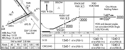
On the example VOR, the missed approach point can be identified only by flying a timed leg using a clock. The climb to 3,000 ft is initiated when the final approach time expires. In general, it is “inadvisable or impossible” to execute a normal landing from the missed approach point of a non-precision approach procedure. The missed approach point is the same for straight-in and circling approaches.
Also note this procedure requires a descent angle greater than 3 degrees.
A common mistake when briefing this type of procedure is to state that the missed approach point is 3.8 NM from the final approach fix, or 12.3 DME. The correct way to identify the missed approach point is by using the times depicted below the profile view. Notice the missed approach point DME is not depicted. In this example, DME is used only to identify the top of descent fix and the final approach fix.
The example procedure KACB VOR RWY 2 was deleted on 8 January 2015.
Scenario #7: VOR at the Airport
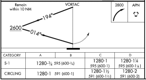
On the example VOR, the missed approach point is identified when the VOR direction flag changes to the FROM indication. The climb to 2,800 ft is initiated at or before the VOR, and the right turn can be made at or beyond the VOR.
Similarly, on an NDB approach, the ADF needle would indicate passing the NDB.
Scenario #8: RNAV without VNAV
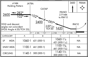
On an LNAV, the missed approach point is the last waypoint depicted in the profile view (RW10).
In case of an early missed approach, no turns are allowed prior to reaching the FIKAM waypoint.
LP is a slightly more precise RNAV guidance level provided by WAAS. The missed approach point is the same for LP, LNAV, and circling approaches.
Scenario #9: RNAV with VNAV
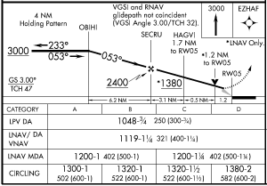
On an LPV or LNAV/VNAV, the missed approach point is that point at which the glide slope intersects the Decision Altitude (DA). In this example, there are two different DAs. The missed approach point for the “top-line” minima only is depicted by “the beginning of the dotted missed approach course line.” The missed approach course for LNAV/VNAV is not depicted in profile view.
In case of an early missed approach, no turns are allowed prior to reaching the EZHAF waypoint.
On an LNAV, the missed approach point is the last waypoint depicted in the profile view (RW05). In this example, it is difficult to distinguish between the missed approach point and the visual descent point (VDP). A pilot would initiate the climb to 3,000 ft between the VDP and RW05. Since no turns are allowed and by definition it is impossible to make a normal landing beyond the VDP, there is no reason to wait for RW05.
The missed approach point is the same for LNAV and circling approaches, but is different from the LPV and LNAV/VNAV. In other words, the example procedure has three different missed approach points. The missed approach course for LNAV is not depicted in profile view.
Scenario #10: LOC/VOR Approach
This is a technicality mentioned in the FAA handbooks. A missed approach point might be defined by a cross-radial from a second NAVAID, and identified during the approach using a second receiver. However, this is extremely rare and I have yet to find any example of this in a non-military procedure. Cross radials are more commonly used to identify a final approach fix. Reference KNFW ILS or LOC RWY 17.
Scenario #11: LOC/DME with RNAV Substitution

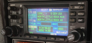
LOC/DME procedures rarely include timed legs or a named fix or intersection to identify the missed approach point. On the example LOC, the missed approach point may be identified only by using DME. Because general aviation aircraft are increasingly dependent on GPS distance information and may not have DME transceivers, the pilot must determine whether the avionics are “suitable” for this procedure. This includes procedures titled “ILS or LOC/DME” which are relatively common. RNAV substitution for the DME is allowed per AC 90-108 to “determine aircraft position relative to or distance from a … DME fix.” Notice it also says, “Pilots must extract waypoints, NAVAIDs, and fixes by name.”
The attached photo of a GNS 430 receiver shows that the I-ORK facility can be identified by name when manually entered as IORK. The small blue square symbol next to the cursor indicates this is a DME facility. Note the DME antenna is located beyond and offset from the final approach path for this procedure. GNS 430 is capable of displaying the distance to this facility, but it will not load the 1 DME fix via the procedures menu for non-overlay approach information. As described in AIM 1‑1‑18(n)(11), “a DME fix will not be in the waypoint sequence on the GPS receiver unless there is a published name assigned to it.”
Scenario #12: ASR Approach
RADAR identification of the missed approach point is provided for ASR approach procedures. However, the location of the missed approach point is not published. Air Traffic Control uses the following phrase to specify the location:
Missed approach point is (distance) miles from the runway.
During the approach, ATC uses this phrase to identify the point:
Over missed approach point. If runway not in sight, execute missed approach.
Scenario #13: PAR Approach
On a PAR procedure, the missed approach point is the intersection of the PAR glide path and a published decision altitude. The terms Decision Altitude (DA) and Decision Height (DH) have the same meaning in this case, and both are MSL altitudes. RADAR identification of the missed approach point is provided using the following phrase:
At decision height.
Scenario #14: Unusual Approaches
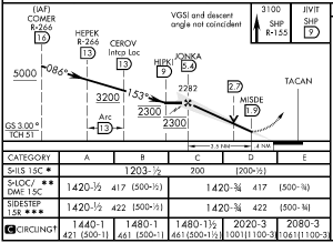
Can you fly this ILS profile? Are you sure? Take a close look at it. What do all those symbols mean? If the glideslope is out of service, how will you identify the missed approach point? Maybe you are equipped for this, but maybe not!
This study guide does not describe all real world situations. There are exotic procedures involving mountainous terrain, restricted airspace, Cat II & III, SDF, IGS, RNP, PRM, and many others. It is always the pilot’s responsibility to understand the procedure before attempting it.
21 responses to “Missed Approach Point Study Guide”
Where is it written that on a ILS missed approach it is ok to bee below DA in process of executing the mist?
Hi Andy, look for AIM 5-4-5(k)(5)(a):
Thank you for publishing this. It is hard sometimes to describe to a student for all different approaches where the missed approach point is. It is easy to sometimes forget all the different approaches there are and the different missed approach procedures as one usually instruct on the same approaches most of the time. Easy to forget when you only fly the same 5-6 approaches over and over again.
I don’t understand Scenario 11. I don’t see anything in the chart for the KORK LOC/DME or the AIM paragraph you cite to preclude the use of GPS to identify the MAP.
AIM 1-2-3(c) doesn’t limit DME substitution only to DME transmitters co-located with certain navaids. And the “Use I-ORK DME” note is a standard chart note when there are multiple DME facilities used – as a reminder for the pilot to pick the right one (See para 8-2-5(f)(3) in the FAA’s Order 8260.19F “Flight Procedures”).
Hi reblok, thank you for the comment. I will attempt to clarify this more in the next revision. The I-ORK 1 DME fix must be identified “by name” according to AC 90-108. My experience with Garmin avionics is that they will not display the localizer ID, but rather some other code such as “MA” in the approach overlay mode. There may be other ways to achieve this and other avionics capable of it.
Hello Robert,
I am looking for some clarification for determining the MAP for a LOC approach that we train at regularly. Our confusion is in regards to KCGZ ILS or LOC/DME RWY 5. A fellow instructor brought to my attention your website and I have spent some time reviewing it. In the PM3, Instrument Flying, sixth edition, chapter 29, page 604, figure 29-9. The MAP for the localizer is clearly marked as the distance from the FAF on the AD of the approach plate. Some people are saying, like you do, that it is the DME marked in the profile view. In most cases the distances are the same, but when they are not, which one takes precedence? We cannot seem to find any other reference to clarify. I look forward to your response. Thank you
Lou
Hi Louis, thank you for writing. The “Airport Sketch Final Approach Course” arrow is such a significant point of confusion that I actually received a phone call, back in June, from an FAA employee who wanted to help me clear this up. My notes from that conversation are now included in Scenario #3 of the study guide. To say it again briefly, the airport sketch usually does not depict a MAP when charted correctly.
The best way to find the MAP is to look at the profile view. The only exception is that the “to MAP” distance and times are sometimes provided in a separate box for timer navigation. The ASA textbook is incorrect if it uses the airport sketch in the missed approach procedure. At KCGZ, the LOC/DME MAP is depicted as TFD 7.5 DME only. This is why it is titled ILS or LOC/DME rather than ILS or LOC. This procedure does not provide a time, speed, and distance method to identify where the missed approach segment begins. The approach track note in this case depicts the distance from the FAF to the runway threshold, which is correct in so far as the “from FAF” distance should depict the threshold location whether or not it happens to be the same location as the MAP. I hope that helps!
Thank you Robert, this is extremely helpful
Dear Robert,
Stumbled on this after being utterly confused by contradicting explanations in my ifr test prep book, and hours between Far/ Aim, IFH and APH. Perfect clarification. Thank you!
Joe
Robert,
Thank you very much for your generosity in sharing this very informative review. I noticed in several of the explanations that you included this phrase: “In general, it is “inadvisable or impossible” to execute a normal landing from the missed approach point of a non-precision approach procedure.” I strongly agree with the thrust of that advice but don’t remember seeing it in any regulatory publication. Do you have a reference?
Additionally, although I know you cannot speak for people who draw the TERPS, do you have any insight as to why they don’t just back up the MAP to a place where an approach could be safely completed? I know they want to give pilots every opportunity to complete the landing but I think the current system has the weakness of enticing the pilot into a difficult (and quite possibly dangerous) maneuver. Again, many thanks for sharing.
Hi Warren, thank you for writing such thoughtful questions. I believe the “official” answers for both of these questions can be found in AIM 5-4-5(L) “Pilot Operational Considerations When Flying Nonprecision Approaches” and its subparagraphs. And to give you a more complete answer, the “place where an approach could be safely completed” is better known as the Visual Descent Point (VDP), not to be confused with a Missed Approach Point (MAP). While some approaches lack a published VDP, I am required at my company to calculate my own VDP for any nonprecision approach by using a 3:1 rule.
Let’s use Scenario #3, above, as the example. KIMT LOC/DME BC RWY 19 has a Minimum Descent Altitude (MDA) of 1,660 ft MSL, and a Height Above Touchdown (HAT) of 478 ft. With 478 ft and a ratio of 300 ft per nautical mile (FPNM), I can see from a quick mental estimation that the runway needs to be in sight at more than 1.5 NM from the threshold. Doing the same division on my iPad calculator, 478 ft / 300 FPNM = 1.6 NM. From the published profile view, I see that the runway threshold is at approximately 1.5 – 0.8 = 0.7 DME. I then add my 1.6 NM + 0.7 NM = 2.3 NM. This gives me a usable VDP of 2.3 DME from the IMT VOR, which is the point where I can make a “normal descent.” Anywhere beyond that point, I am not allowed to initiate a straight-in landing.
I saw this now as I was preparing material for my own student. This is very helpful and clearly described. Super appreciate you taking the time and effort to post this material. It’s super useful.
This is an excellent guide, but I have one procedure that continues to confuse me with regard to MAP identification. The VOR 18 at KTYQ. It’s not a VOR/DME, but all the fixes are indicated as distances from he Brickyard VOR. On the plan view the MAP appears to be between the 14.4 and 15.5 DME from Brickyard and there are no times listed. For a non precision approach I understand I should be at the MDA (1320′) but what is the position indication for the MAP for this approach? Any thoughts or feedback for this situation and is this unusual?
Hi Chris, thank you for writing. You can safely assume the last fix in the profile, VHP 14.4 DME, is the MAP. From my first glance, I would have to say the December 2020 chart cycle for that procedure has a profile view with the dashed line misplaced such that it doesn’t quite align with any of the fixes. I went the extra step to look up the exact location from the Airport Procedures Information Gateway. It shows “VHP 14.43 DME”. If you are interested in improving the chart, you can contact the email address listed in the TPP or the Aeronautical Information Services website. They can take care of it within one or two cycles.
What a really nice set of IAP scenarios to cover for training! One question: In Scenario 4, on the missed you have to first reach your straight out climb altitude of 1100ft before the climbing left turn can begin, correct/agree? Similar climb THEN turn on the missed’s of scenarios 1, 2 and 11. The turn part is mentioned in 2 and 4, but it reads like you are saying you can turn as soon as you cross the map, but you have to satisfy your straight out requirement first….
Thank you and again great training guide.
Hi Andy, while there is always room for clarification, this study guide neither instructs nor implies ignorance of any minimum altitude. This is a focused discussion about the missed approach point. After identifying and locating this point, a pilot may climb prior to this point and may turn after this point. The missed approach procedure must be followed. Some procedures include a maximum altitude preventing a climb, while others have a minimum altitude or direct course preventing a turn. With that said, the scenario #4 does not have a “straight out requirement”. It would be most precise to say that the pilot must both meet the climb requirement and cross the missed approach point before turning. I will consider whether that degree of precision is needed for future revisions.
Thanks for all your help and clarification. I can envision a scenario when a missed approach requires an immediate climbing turn, say to the left. If the pilot becomes disoriented or otherwise unable to complete the approach and he decides to fly the missed then there can be a problem depending on how far along he is on the approach. If he just passed the runway threshold and starts his climbing left turn and the tower is on the left side of the runway then that could be a serious problem!
Robert, if you fly the localized approach and you do not have DME , RNAV and there are no cross radials only VOR/ILS receiver , clock , marker receiver can you use the outer marker beacon to identify your FAF and when do you start your timer ? At the first tone or after a couple of seconds?
Hi Michael, yes the outer marker beacon is a valid NAVAID for determining the time from the FAF to the MAP. Likewise, a compass locator (LOM) can be used if your aircraft is ADF equipped. The exact technique depends on your equipment and ground speed. Whether you have a PFD display, flashing lights, or just sensitivity or volume controls, it will be possible to identify the outer marker without any large errors. Your ground speed estimate is likely not accurate within a couple of seconds, and that is assumed in the design of the approach minimums.
This is a great resource. Thank you very much. Can you provide a reference to clarify that the MAP for an ILS or LOC/DME approach is the last fix identified in the profile view when the dashed missed approach track is shown for the ILS (the intersection of the ILS DA and glideslope)?
E.g. the ILS Z or LOC Z RWY 20R at Fairbanks International (PAFA).
Hi Lon, thank you for this specific question.
The FAA charting convention is to depict only one missed approach point, and then the non-precision MAP is the last fix, waypoint, or navaid on the final approach course. I don’t think this is explained by the FAA anywhere, which is one of several reasons I created my study guide.
For an official reference, the FAA does have textual descriptions of each terminal procedure, which is the basis for the charts. Also note TERPS specifies the LOC MAP is never beyond the landing threshold.
The LOC MAP for the specified procedure is officially “RW20R OR AT I-FAI 2.01 DME”, which allows RNAV identification without the use of the DME station.